It took a while, but I’ve finally finished the Hoist Beam and Conveyor for the Workshop.
My goal was to have a hoist that I could extend out onto a cantilevered beam to move wood between the Workshop loft and the ground level. My design criteria was to be able to safely move at least 4 sheets of furniture grade plywood in a single lift. At 75lbs per sheet, I needed to be able to lift 300lbs with a 5X safety factor (AKA 1500lbs).
The challenge was two-fold: First, I wanted the beam to extend at least 5 feet from the front of the Workshop so that I could easily lift material as long as ten feet long. Anything longer than that will require a bit of manipulation, but I’m hoping that it’s rare that I have material that long. The five foot requirement created a fairly long section of beam without any support – the beam needed to be strong.
The second challenge, somewhat related to the first, but, in some ways conflicting with the first, is that there weren’t any solid attach points in the Workshop loft, other than the loft door header, due to the truss system that was used. With 300 lbs plus the weight of the beam and hoist, a hefty suspension system needed to be constructed.
I am happy to say that I was not only able to meet my goal, but, based on my testing, have exceeded the requirement by a large margin. My initial test, of course, was to simply place enough weight to gain some confidence that the beam wasn’t going to fall down during stress testing. I did this by slowly stepping on a lowered sling while Kerry used my laser range finder to measure the beam deflection. This test proved the beam stiff enough to try a full weight test.
For the full weight test, I lifted my DR Power Wagon which weighs 330 lbs. I didn’t lift it all the way to the top, but did lift it several feet off the ground. In my first test I measured 3/16″ deflection at the end of the beam. 3/16″ over a 60″ span is l/320. Recommended design limits for wood beams is not to exceed l/180 with l/240 a very common design value. I felt that these results met my criteria, but didn’t have enough margin to make me happy. In the photos below, you’ll see that the beam has a stainless steel wire rope and strut stiffener that acts as a backbone for the beam. I had initially tightened the backbone just enough to make the cable ‘taut’. After these initial results, I decided to tighten the cable a bit more (working load limit of the cable is well over my 1500lb design point). After this adjustment, the deflection, with the 330 lb load, was now only 1/8″ or l/448 – very satisfying, indeed.
In the photos below, you’ll see the beam, the internal structure and the conveyor used to haul the hoist in and out on its track. I’m very pleased with it and can now shift my focus to hauling material to finish off the loft and store my wood in an organized way.
UPDATE: Jan. 14, 2018
At the request of Ash, I’m adding a couple of photos showing how the hoist is attached to the beam. In the photos below, you can see the hoist and 2×2 iron squares. The squares are cut long enough to reach across the two tracks. The hoist is attached to the bottom of the squares using the threaded mounting bushings already present in the hoist mounting plate. These are metric bolts and I replaced the originals with some hardened one that had properly cut threads in them (the originals were not exactly top quality, if you know what I mean!). The track wheels have a post that is normally used to hang doors from, but I put the post through the iron square and used elastic stop nuts to prevent them from loosening. These I tightened to where there was just a slight clearance between the top of the square and the bottom of the track. This ensures that the hoist can’t jump out of the track if there was a sudden bump or release.
Let me know if you have any questions about this…
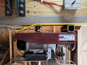
Detail of hoist attachment to beam.
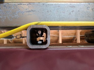
Closeup of 2×2 Iron Square.


![[img src=https://tomstudwell.com/wordpress/wp-content/flagallery/galileothermometer/thumbs/thumbs_gt_0004.jpg]1730](https://tomstudwell.com/wordpress/wp-content/flagallery/galileothermometer/gt_0004.jpg)
![[img src=https://tomstudwell.com/wordpress/wp-content/flagallery/galileothermometer/thumbs/thumbs_gt_0007.jpg]1580](https://tomstudwell.com/wordpress/wp-content/flagallery/galileothermometer/gt_0007.jpg)
![[img src=https://tomstudwell.com/wordpress/wp-content/flagallery/galileothermometer/thumbs/thumbs_gt_0001.jpg]1520](https://tomstudwell.com/wordpress/wp-content/flagallery/galileothermometer/gt_0001.jpg)
![[img src=https://tomstudwell.com/wordpress/wp-content/flagallery/galileothermometer/thumbs/thumbs_gt_0002.jpg]1450](https://tomstudwell.com/wordpress/wp-content/flagallery/galileothermometer/gt_0002.jpg)
![[img src=https://tomstudwell.com/wordpress/wp-content/flagallery/galileothermometer/thumbs/thumbs_gt_0003.jpg]1420](https://tomstudwell.com/wordpress/wp-content/flagallery/galileothermometer/gt_0003.jpg)
![[img src=https://tomstudwell.com/wordpress/wp-content/flagallery/galileothermometer/thumbs/thumbs_gt_0005.jpg]1350](https://tomstudwell.com/wordpress/wp-content/flagallery/galileothermometer/gt_0005.jpg)
![[img src=https://tomstudwell.com/wordpress/wp-content/flagallery/galileothermometer/thumbs/thumbs_gt_0006.jpg]1310](https://tomstudwell.com/wordpress/wp-content/flagallery/galileothermometer/gt_0006.jpg)
![[img src=https://tomstudwell.com/wordpress/wp-content/flagallery/galileothermometer/thumbs/thumbs_gt_0008.jpg]1270](https://tomstudwell.com/wordpress/wp-content/flagallery/galileothermometer/gt_0008.jpg)
![[img src=https://tomstudwell.com/wordpress/wp-content/flagallery/hoistbeam/thumbs/thumbs_hb_0011.jpg]55700Outside view of the Beam and Hoist](https://tomstudwell.com/wordpress/wp-content/flagallery/hoistbeam/hb_0011.jpg)
![[img src=https://tomstudwell.com/wordpress/wp-content/flagallery/hoistbeam/thumbs/thumbs_hb_0003.jpg]55900Inside view of the Beam and mounting structure.](https://tomstudwell.com/wordpress/wp-content/flagallery/hoistbeam/hb_0003.jpg)
![[img src=https://tomstudwell.com/wordpress/wp-content/flagallery/hoistbeam/thumbs/thumbs_hb_0004.jpg]53790View from the other side of the beam showing conveyor.Note the gear motor, pulleys, and cable. The motor can pull the hoist, fully loaded, in and out on its track.](https://tomstudwell.com/wordpress/wp-content/flagallery/hoistbeam/hb_0004.jpg)
![[img src=https://tomstudwell.com/wordpress/wp-content/flagallery/hoistbeam/thumbs/thumbs_hb_0005.jpg]53190Updated Truss system.These trusses need to support both a lifting and a gravity force.](https://tomstudwell.com/wordpress/wp-content/flagallery/hoistbeam/hb_0005.jpg)
![[img src=https://tomstudwell.com/wordpress/wp-content/flagallery/hoistbeam/thumbs/thumbs_hb_0006.jpg]51980View of inside stiffening strut and hoist power cable management system.The stiffening strut can be adjusted by the turnbuckle shown in the photo. The power cable management system keeps the cable retracted while the hoist is moved between the extreme ends of the beam. This photo shows the position with the hoist fully extended on the beam.](https://tomstudwell.com/wordpress/wp-content/flagallery/hoistbeam/hb_0006.jpg)
![[img src=https://tomstudwell.com/wordpress/wp-content/flagallery/hoistbeam/thumbs/thumbs_hb_0007.jpg]50560Here the hoist has been retracted to just short of center.](https://tomstudwell.com/wordpress/wp-content/flagallery/hoistbeam/hb_0007.jpg)
![[img src=https://tomstudwell.com/wordpress/wp-content/flagallery/hoistbeam/thumbs/thumbs_hb_0008.jpg]48870With the hoist retracted just past center, you can see the cable shift position in the guide.](https://tomstudwell.com/wordpress/wp-content/flagallery/hoistbeam/hb_0008.jpg)
![[img src=https://tomstudwell.com/wordpress/wp-content/flagallery/hoistbeam/thumbs/thumbs_hb_0009.jpg]48270Here is the cable position with the hoist fully retracted inside. You can see the counterweight bucket in the background. It contains about 7 1/2 lbs of gravel.](https://tomstudwell.com/wordpress/wp-content/flagallery/hoistbeam/hb_0009.jpg)
![[img src=https://tomstudwell.com/wordpress/wp-content/flagallery/hoistbeam/thumbs/thumbs_hb_0010.jpg]47630The cable position with the hoist fully extended again.](https://tomstudwell.com/wordpress/wp-content/flagallery/hoistbeam/hb_0010.jpg)
![[img src=https://tomstudwell.com/wordpress/wp-content/flagallery/hoistbeam/thumbs/thumbs_hb_0012.jpg]48620Close up of the exterior structure.](https://tomstudwell.com/wordpress/wp-content/flagallery/hoistbeam/hb_0012.jpg)
![[img src=https://tomstudwell.com/wordpress/wp-content/flagallery/hoistbeam/thumbs/thumbs_hb_0013.jpg]46550My first REAL load! Moving some wood up to the loft!](https://tomstudwell.com/wordpress/wp-content/flagallery/hoistbeam/hb_0013.jpg)
![[img src=https://tomstudwell.com/wordpress/wp-content/flagallery/hoistbeam/thumbs/thumbs_hb_0014.jpg]46640Almost there.](https://tomstudwell.com/wordpress/wp-content/flagallery/hoistbeam/hb_0014.jpg)
![[img src=https://tomstudwell.com/wordpress/wp-content/flagallery/hoistbeam/thumbs/thumbs_hb_0015.jpg]45660Delivered!](https://tomstudwell.com/wordpress/wp-content/flagallery/hoistbeam/hb_0015.jpg)
![[img src=https://tomstudwell.com/wordpress/wp-content/flagallery/hoistbeam/thumbs/thumbs_hb_0016.jpg]45710AND, with the hoist now operational, I loaded ALL the tools that have been collecting in the loft in one trip!Almost 200lbs of tools!](https://tomstudwell.com/wordpress/wp-content/flagallery/hoistbeam/hb_0016.jpg)
![[img src=https://tomstudwell.com/wordpress/wp-content/flagallery/hoistbeam/thumbs/thumbs_hb_0001.jpg]45740Here's a view of getting ready to pull the beam up to the trusses.Using the hoist itself...](https://tomstudwell.com/wordpress/wp-content/flagallery/hoistbeam/hb_0001.jpg)
![[img src=https://tomstudwell.com/wordpress/wp-content/flagallery/hoistbeam/thumbs/thumbs_hb_0002.jpg]44620Another view of ready to raise the beam.](https://tomstudwell.com/wordpress/wp-content/flagallery/hoistbeam/hb_0002.jpg)
![[img src=https://tomstudwell.com/wordpress/wp-content/flagallery/watermonitorproject/thumbs/thumbs_rtx_0001.jpg]10.8k0Photo of the RTX4100 moduleThe module is only 18mm x 30mm including a built-in PCB antenna - it is a COMPLETE WiFi system!](https://tomstudwell.com/wordpress/wp-content/flagallery/watermonitorproject/rtx_0001.jpg)
![[img src=https://tomstudwell.com/wordpress/wp-content/flagallery/watermonitorproject/thumbs/thumbs_wmz_0002.jpg]10.6k0Here's the circuit board before mounting components.The circuit board is 3.8" x 2.5" and holds the complete system!](https://tomstudwell.com/wordpress/wp-content/flagallery/watermonitorproject/wmz_0002.jpg)
![[img src=https://tomstudwell.com/wordpress/wp-content/flagallery/watermonitorproject/thumbs/thumbs_wmz_0001.jpg]10.6k0Here is the finished circuit board for the Water MonitorThis shows the module along with the interface components that I added. The battery is used to provide backup power for the 32KB of RAM used to log samples. The large black module is a solid state relay to control the Water Softener.](https://tomstudwell.com/wordpress/wp-content/flagallery/watermonitorproject/wmz_0001.jpg)
![[img src=https://tomstudwell.com/wordpress/wp-content/flagallery/watermonitorproject/thumbs/thumbs_wm_0002.jpg]10.5k0Here's a close up of the Water Monitor installed.](https://tomstudwell.com/wordpress/wp-content/flagallery/watermonitorproject/wm_0002.jpg)
![[img src=https://tomstudwell.com/wordpress/wp-content/flagallery/watermonitorproject/thumbs/thumbs_wm_0003.jpg]10.5k0Here is the whole installation.You can see the water hardness monitoring probes, the connection to the water softener, and the water pressure sensor.](https://tomstudwell.com/wordpress/wp-content/flagallery/watermonitorproject/wm_0003.jpg)
![[img src=https://tomstudwell.com/wordpress/wp-content/flagallery/watermonitorproject/thumbs/thumbs_wm_0005.jpg]10.5k0Here's a look at the user interface after querying the info from the Water Monitor.The data on the left is the information that is saved with each sample. Sampling occurs at 10 minute intervals.Note that the coarse text is due to the way I captured the screen shot. The real web page is high quality web text...](https://tomstudwell.com/wordpress/wp-content/flagallery/watermonitorproject/wm_0005.jpg)