More Woodturning…

Here are my latest turnings.  The photos are captioned and should be self explanatory.

Starting with the most current…
Click to view larger image.

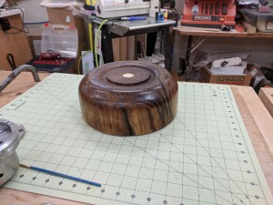
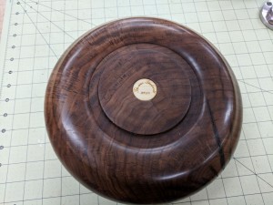
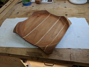
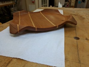
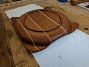
I decided to try a serving platter as a birthday gift. This is made from sections of Red Grandis separated by progressively thinner layers of hard maple.
Click to view larger image.

Side view showing the profile and layering.

Click to view larger image.

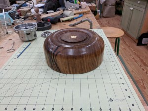
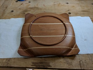
Bottom profile.

Click to view larger image.

And signed, of course! I didn’t use my laser cut medallions here because I didn’t want to accidentally cut through the bottom. There ‘may’ have been enough thickness left, but I wasn’t taking any chances!

Click to view larger image.

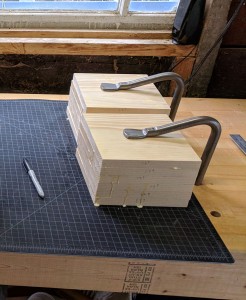
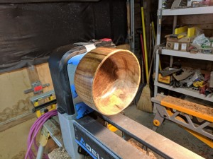
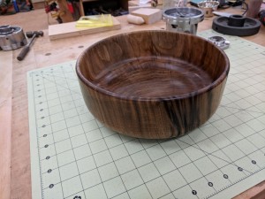
What do you do with a pile of pine boards glued together?

Click to view larger image.

Why, you make a bowl, of course!

Click to view larger image.

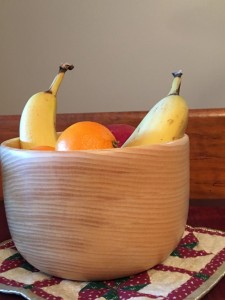
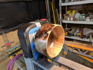
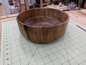
Side view.

Click to view larger image.

I love the grain pattern that the stacked boards make!

Click to view larger image.

Gotta sign it, right?
By the way, this was before I was confident enough to turn off the bottom tenon…
Click to view larger image.

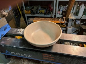
I got a nice collection of Maple chunks that my sister saved from her fallen tree. I decided to give a piece of it back to her…
Click to view larger image.

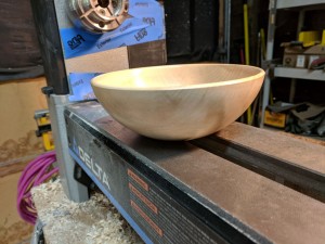
Maple Bowl, side view.

Click to view larger image.

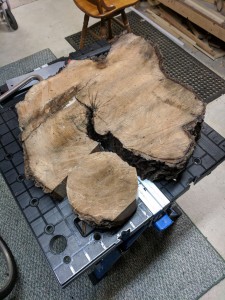
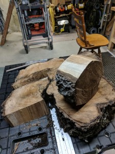
I got a slice of a butternut tree that was sitting in a friend’s pile of firewood. It seemed, if nothing else, it would be a good practice piece of wood. Note that I’ve marked into sections that could be isolated into turnings. The piece in the foreground has already been cut to a rough cylinder.
Click to view larger image.

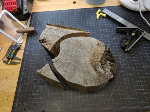
I used a sawzall to cut it into sections I could put on my small bandsaw so I could cut them into rough cylinders…
Click to view larger image.

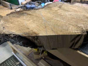
Next section isolated and cut on the bandsaw. Note that the slice of tree wasn’t cut neatly parallel. I’ll have to speak to my friend about how to cut firewood!
Click to view larger image.

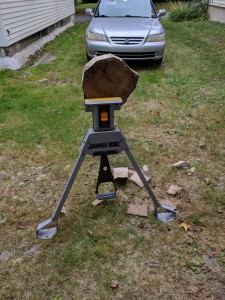
These last two sections are going to be a problem. Finding the tangent line to cut them apart and leave enough wood in both of them took some study.
Click to view larger image.

Finally, the last piece wouldn’t fit in my tiny bandsaw so I had to ’round’ it by chopping off the corners with the sawzall.
Click to view larger image.

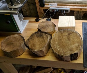
Four chunks from the original slice. Not bad. Now, let’s see what I can do with them!

Click to view larger image.

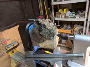
I started with one that was the second smallest. The smallest was too severely wedged for my confidence level…
Click to view larger image.

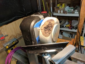
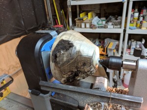
Roughed down to something resembling the outline of a bowl. Pretty good start considering how much bark still remained.
Click to view larger image.

Looking pretty good. Still have to do the inside, but this is promising.

Click to view larger image.

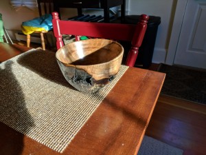
Wow! It actually came out! The outer bark and finish has a lot of CA glue holding it together, but it looks good.
Click to view larger image.

Ok, let’s try the ‘wedgie’ one!

Click to view larger image.

Highly wedged and lots of bark! Don’t know about this one…

Click to view larger image.

Gosh, maybe it will be ok! Lots of bark, but it is interesting!

Click to view larger image.

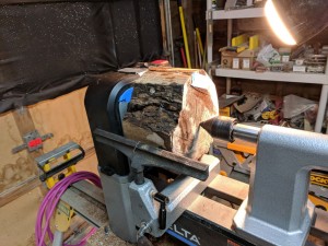
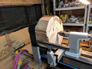
Now on to the midsized one… this one is fairly ‘civilized’, but took a lot of CA glue to seal the large cracks in it. You can see the masking tape on the surface to keep the CA glue from running out before it cured!
Click to view larger image.

Yup, looks like this one will come out too!

Click to view larger image.

Another view showing the bark and cracks.

Click to view larger image.

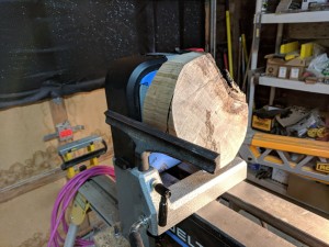
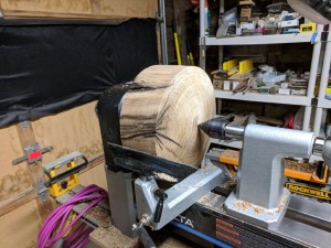
Finally on to the big chunk! Hmmmm, this may be a problem for this little lathe! That chunk is pretty heavy and it is NOT balanced!
Click to view larger image.

Well, I managed to get it round, but it was still out of balanced so I couldn’t get the speed high enough for me to get a good finish.
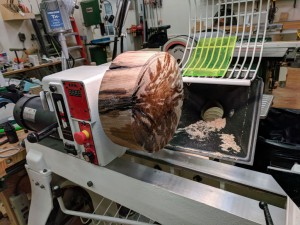
Click to view larger image.

So, I brought it back to HIW workshop to finish on the big lathe. Note more CA glue to fix cracks that occurred since rough turning.
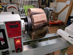
Click to view larger image.

I had to use my big faceplate and big screws to mount it as I wasn’t confident that it would hold together with all the cracks.
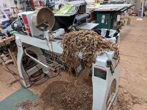
Click to view larger image.

I’ve heard that you know that you’re cutting correctly when the shavings come off in streamers. Well, this pile was from one pass where the streamers literally flew over my shoulder while turning. It was quite thrilling!
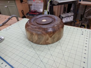
Click to view larger image.

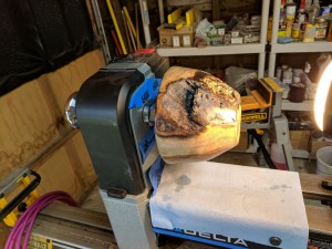
And it came out! I decided to make the mounting foot a ‘design detail’ because I didn’t have the set up to turn it off reliably.
Click to view larger image.

Butternut is a lovely wood. I’m glad I rescued this piece from the firewood pile!

Click to view larger image.

Another side view

Click to view larger image.

Laser engraved and cut ‘signature’ medallion.

Click to view larger image.

More lovely character of this piece.

Click to view larger image.

One final view.


Upgrade to CNC Router

In my previous posting on updating my CNC Router, I replaced the mechanical system with a whole new system that was more stable structurally than my original home brew system.  I mounted the new mechanical system on the old system’s frame (as it was mobile and could be folded up for storing) and kept the old system’s electronics.

I soon found that the old electronics were not going to work very well with the new mechanicals.  The new mechanism had a lower resolution movement per step of the stepper motors (to allow faster movement), but this meant the electronics had to be modified for finer steps per revolution (microstepping) and the old electronics were implemented with low cost stepper drivers and could not drive the motors fast enough with the increased stepping rate.  I concluded that it was time to totally redesign the electronics to meet the improved stability of the new mechanicals.

I purchased the electronics in the Winter of 2016 but only recently got around to working on it.

The results are SPECTACULAR!  Not only is the new system a lot faster (3-5X), it is also a lot quieter with the faster switching electronics.  The resolution and accuracy appear to be excellent and MUCH smoother!

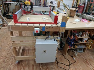
Here is the old hybrid system with the new electronics sitting on the table next to the router.  I did this to make sure everything was tuned up before I tore apart the old electronics.

Click to view larger photo.

CNC Router after previous upgrade and readying for new electronics.

The results were very promising but only after I also replaced the Z Plate in the Shapeoko mechanicals.  The old Z Plate had too much flex and would not be able to handle the work loads I have in mind.

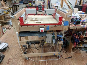
Here is the new system with the new electronics and enclosure with the wiring cleaned up and routed through cable carrying drag chains.

Click to view larger photo.

System upgraded with new electronics and cleaned up wire routing.

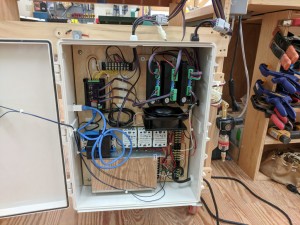
Here is a closeup of the new electronics in the enclosure.  The drivers are much more powerful and the power supply for the motors was doubled in voltage (48V) to increase the stepping speed.

Click to view larger photo.

Closeup of the CNC Router upgraded electronics.

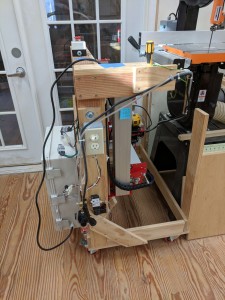
Here’s the new unit stowed.  It tucks into its spot a lot closer now since the platform closes to full vertical now and I got rid of the attached display and keyboard.  The new system uses Virtual Networking Console (VNC) so I can run the system from my laptop without any wired connection.

Click to view larger photo.

CNC Router stowed away. Fits much better than the previous two versions!

Finally, for the first test, I decided to try the Pottery Stamp I’ve made with my original router. I checked in with Matt and asked if he wanted any changes before I made another one.  As it turned out, he wanted a smaller version, which made this new one much more challenging!  Happily, the new router was up to the task and produced a very high quality cutting with walls as thin as 18mil and wall height of 187.5mil (10:1 aspect ratio)!

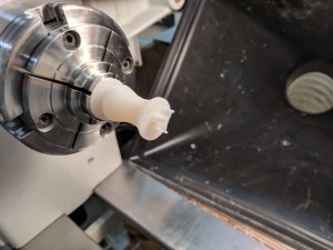
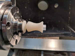
Having made some progress on my wood lathe, I couldn’t stop there and simply HAD to turn a better handle on the stamp.  Here ya go:

Click to view larger photo.

Closeup of first test of the new CNC router electronics. Excellent detail. The wall thickness is 0.018″ (0.457mm) with a height of 3/16″ (10:1 aspect ratio!)

Click to view larger photo.

Side view of the first test of the CNC Router, turned on my wood lathe.


3D Printer for the Little House in the Village!

The 3D printer that ‘Santa Claus’ brought to us in December, proved to be SOOOOO useful, I knew that I couldn’t live without one at the Little House in the Village (LHV)!  So…

I ordered one about 8 weeks ago and it finally arrived last week!  Having built the previous one, with the help of the entire family, this one was a breeze to assemble, although it did take longer in elapsed time doing it single handedly (about 5-6 hours).

I considered going with a different printer, lower cost and not a long lead time, but the quality and features (Auto calibrate being the most significant) of the Prusa convinced me to stick with a winner!

I noticed a few improvements or tweaks in the design since the previous unit telling me that the company is constantly monitoring their product and continuously making improvements – a very good sign!

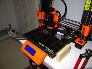
So here it is:

Click to view larger image.

Finished Printer with miscellaneous parts. Note the mounted camera to the left.

I did make a mistake in assembly that cost me during the calibration cycle (you can see a nasty dig in the right hand side of the platen).  This can be replaced, but, so far, I haven’t printed anything so wide that I would need that area of the bed.  Since then I was able to realign the assembly and was able to perform a good calibration of the unit.  I think this unit has much better print quality than the first one.

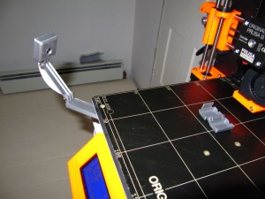
I switched cameras on this one, using the small camera designed specifically for the Raspberry Pi.  The reason for this is that I discovered that the camera really needs to be mounted on the platen, otherwise the timelapse videos will drive you nuts as the workpiece keeps moving with respect to the camera.  With this arrangement, the camera and workpiece have the same frame of reference and you can easily see it being ‘built’.

The camera mount came from www.thingiverse.com/thing:2113975.  However I made a mistake printing this in PLA.  The part connected to the platen ‘drooped’ after I printed a couple of ABS parts (which has a much hotter platen).  I’ve since reprinted the one piece in ABS.

Click to view larger image.

Closeup of camera (Raspberry Pi Camera V2.1) and filament dust filter enclosure. This is a hinged piece printed in a single pass.

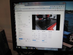
The 3D Print server works very well with this camera:

Click to view larger image.

View of screen running 3D Printer server, complete with video!

Having a queue of projects and add-ons for the printer, I spent the next couple of days printing various items…

Click to view larger image.

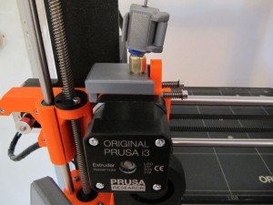
Close up of Extruder Filament guide adapter plate. Teflon tubing connects this to the filament dryer filament feed guide. Also note the filament dust filter. Normally this will be located just before the upper feed guide as the tubing will keep the filament dust free after that.

Click to view larger image.

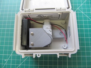
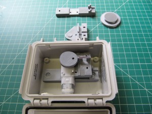
3D printed drip valve, just waiting for the PCB to control it.

Click to view larger image.

Miscellaneous parts printed on the new printer. Overall the quality appears better than the printer at the House In The Woods. Probably due to better calibration and newer printer firmware.

With my limited space at LHV, I knew that the printer would be relegated to the garage/workshop, which is both dusty and humid.  Humidity and 3D filaments don’t mix well – or, I should say, they mix TOO well with 3D filaments LOVING to absorb any moisture in the air.  So, I needed a setup where the filament was kept in a dry spot.  After some research, I discovered that Food Dehydrators are very popular mods for 3D printers and this led me to this next series of photos…

Click to view larger image.

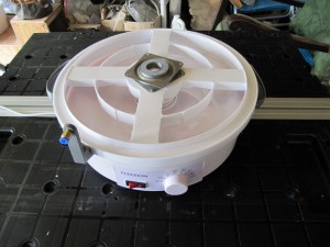
Filament dryer base (Cake Transporter) with final modifications sitting on top of unmodified Food Dehydrator. Note lazy susan bearing and 3D printed hub to keep spool aligned and turning easily.

I found a Food Dehydrator and a plastic Cake Transporter that appeared to be ‘right sized’ for this application.  The Food Dehydrator was PERFECTLY sized with the cake transporter base fitting just inside the rim of the dehydrator, I didn’t need any modifications for the dehydrator base.

I was then able to cut out openings in the cake transporter base with a flush cutting router bit in my trim router.  The lazy susan, used to allow the spool to spin freely, was also ‘off the shelf’ and it just took a couple of simple 3D printed add-ons to complete the dryer!

Click to view larger image.

Filament dryer base (Cake Transporter) with final modifications sitting on top of unmodified Food Dehydrator. Note lazy susan bearing and 3D printed hub to keep spool aligned and turning easily.

Click to view larger image.

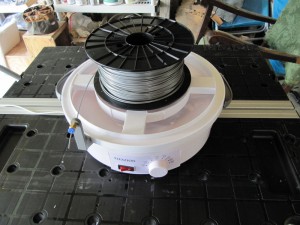
Filament Dryer with spool and filament guide. The fitting holds a teflon tube that guides the filament down to the extruder.

Click to view larger image.

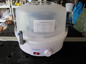
Completed Filament Dryer, drying a spool of PLA.

I’m trying a simpler enclosure (a large cardboard box) this time around, but I may go the same route as HIW as the cardboard box is a bit too rickety.  We’ll see and I’ll update this when I reach a conclusion…


WordPress theme: Kippis 1.12