I’ve been using my CNC router pretty steadily since I first made it about 2 1/2 years ago and while it’s been quite useful and productive, the old DIY version has a few ‘idiosyncrasies’ that I wanted to address. The more severe of these issues were:
- With the main Y and Z tracks formed by two parallel pipes held in place with common 2X lumber, the spacing of the pipes would vary fairly largely as the humidity changed. When expanding, the pipes would push the bearing wheels outward making the tracking tight, but the worst effect was after the wood shrunk again, the tracking would then be loose and have to be re-aligned before I could use the tool.
- The Z axis, sandwiched between the Y Gantry plates ended up making the Z truck relatively narrow and, as a result, the router motor wasn’t held as rigidly in the X direction as I would have liked. The effect of this were holes that weren’t round, inaccurate tracking on curves, and a system that was too ‘sloppy’ to try to mill aluminum – something I’d really like to try.
I didn’t see an easy way to modify what I had, since these problems were fundamental to the DIY implementation. So, looking around, I found a router made by Carbide 3D that looked like it would meet my needs and further discovered that the mechanism (the part I really needed to replace) was available in kit form from Sparkfun!
This new mechanism is about 2/3s the size of the Old router (16×16 vs 24×24), but I never routed anything ranging larger than 15″ on the old one. Hence the new one, being much more solid, promising faster travel speeds, AND not requiring realignment every time I want to use it, seems much more valuable to me.
I decided that this project needed to be done in three phases:
- Replace the old CNC router with new mechanicals, reusing the motors, electronics, and base from the old system. I’d have to add another motor to the mix since the new system uses two motors for Y Axis.
- Replace the old base with a new base constructed out of T-Slot aluminum extrusions so that I would have a robust structure to which I could hold down soft metal parts for routing. I’ll mount this on a cabinet that I can wheel around as conveniently as the current CNC router base.
- Finally, to achieve the full capability to route soft metals, replace the electronics with a faster processor, high voltage power supply, and more powerful drivers.
The first step, then, was to strip the old CNC router of it’s mechanicals, but, before I did, I needed to do two things:
- Flatten the base of the old router so that the new mechanicals would have a flat base to rest on. The older bed had high spots as high as 1/32″ due to cupping of the slats I had installed. Originally these had been trimmed to +/- 0.005″ over the entire bed.
- Make an adapter to mount the Bosch Colt router motor in the new system. The new kit included an adapter for a Dewalt DW611 compact router, but the DW611 router is slightly smaller than the Bosch. I really like the Bosch motor and have invested in a number of expensive chucks primarily for CNC routing.
So, using the Old Router to plane its bed:
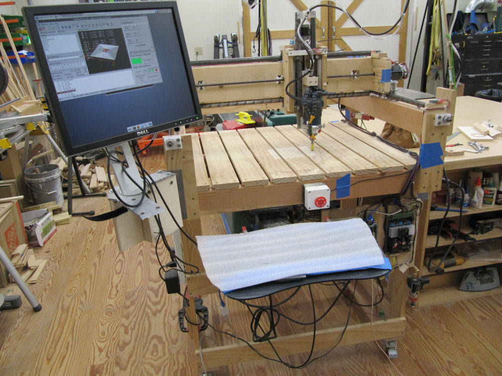
Old CNC router planing its work surface to flat.
I’ve got a new flat surface and, taking a nice solid piece of hard Maple, I machined an adapter for the Bosch router. I can buy an aluminum one, but these are shipped from China and I didn’t want to wait for weeks to get one. This one will serve nicely until I decide to upgrade to aluminum…
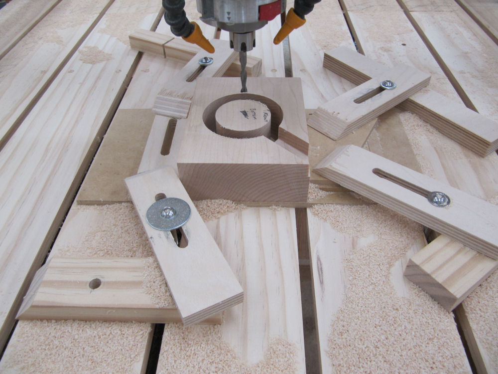
Old CNC Router working on its last job. Making the mounting adapter for the NEW ROUTER!
By the way, the chunk of Maple was glued to a 1/4″ thick MDF waste board using CA glue and then the waste board was sanded off on my thickness sander. Easy hold down technique!
I then stripped off the old gantry and removed the stepper motors. WOW! What a job THAT was! I had used Loctite Green on all the mounting nuts and set screws and it was a chore to free these up!
Building the kit was easy and in no time I had a new mechanism mounted on the old base!
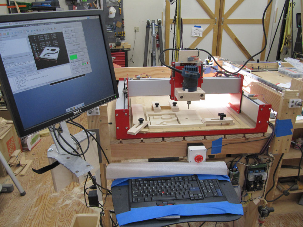
New CNC Router mounted on old stand
Here’s a closer view. The router had just finished its first job, a test pattern I used to test and trim the old router. This first pass on this new router actually came out better than the LAST pass on the old router! Yippee!
New CNC Router finished first job with excellent results!
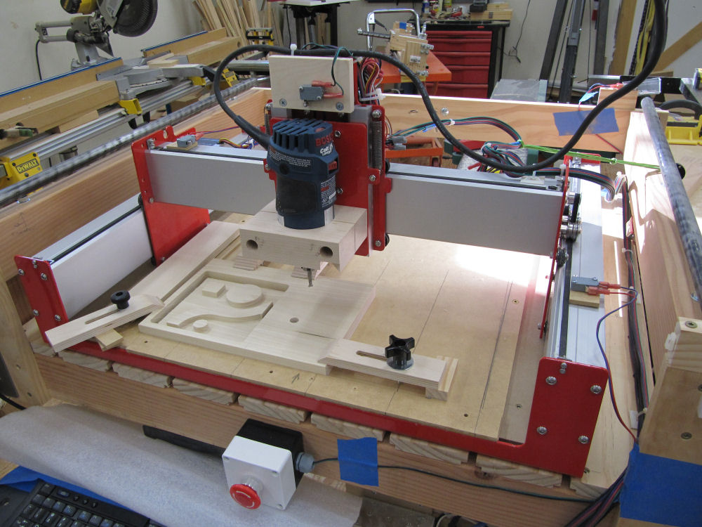
This new router uses a different drive mechanism than the old one. The old one used conventional Acme screws driven by the stepper motors. This new one uses GT2 treaded belts and the motor has a matching treaded pulley that literally pulls the assembly along the stationary belt. The belt is very strong, but has a coarser pitch than the Acme screws I used so that the steppers need to be micro-stepped about 4 times for each step of the previous system. This will give me faster travel (something I need to mill aluminum) but, until I replace the electronics, a slightly coarser finish. Oh well, something to look forward to…
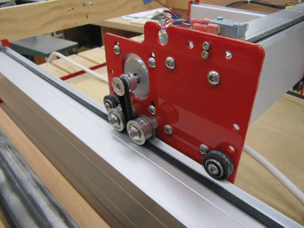
Drive system for new CNC Router, Y axis shown.
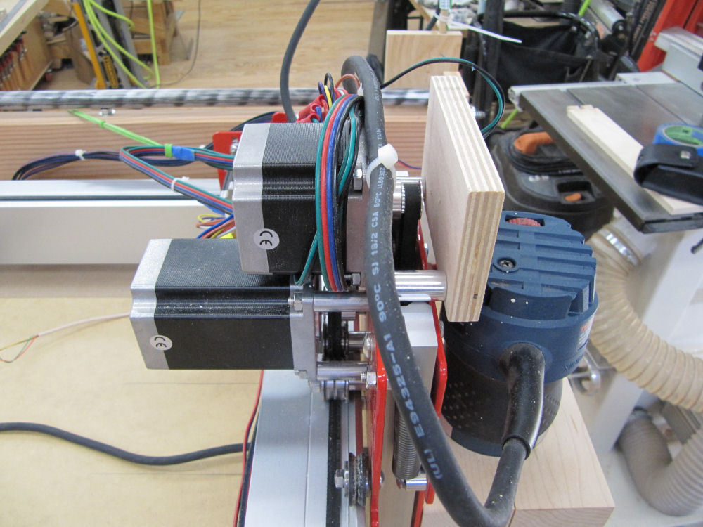
New Router X & Z axis drives.
Finally, I can use the same folding setup from the previous router to fold up the system for storage:
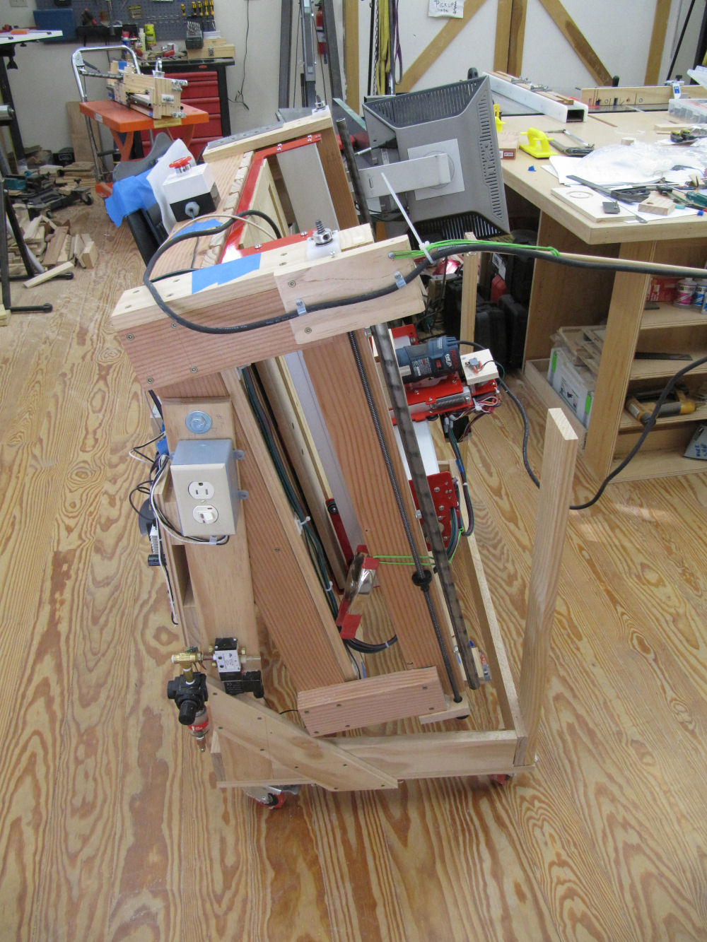
New CNC Router folded up to put away.
I’ll be using this version for a while until I’m sure I’ve gotten it completely stable and then move on to the next phase of the project.
Leave a Reply