Construction of the back for Kate’s Chair

I received a question about how the back of Kate’s Chair was constructed.  I decided that I’d post the ‘secret’ method that I used  ;-)

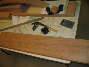
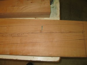
I used a single piece of wood to make both rails and selected the section to maximize the grain continuity between the two sides. You can see the center line following the center of the grain pattern.

Click to view larger image.

Hunk of Cherry used to make side rails for back of chair.

Click to view larger image.

Close up of grain pattern.


Click to view larger image.

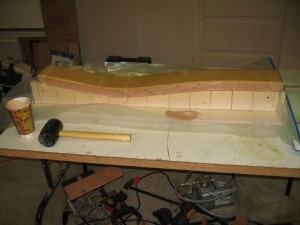
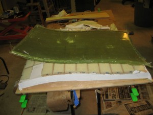
The section sliced and laminated.

The section has been sliced into multiple thin layers, glued back together, and pressed into a vacuum bag against a form shaping the piece into the curve for the back.  The diagonal lines were used to keep the pieces in order in case they were dropped before gluing.  This is a trick from the old punched card days :-)

Click to view larger image.

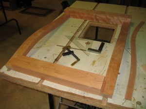
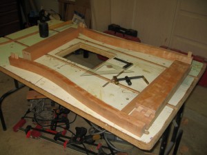
Side rails sliced into two rails and being fitted to head and bottom boards.

Note the extra slice on the side, this will be used as a guide to make the inside support form.  Also note the curve of the tailboard marked on the wooden block.

Click to view larger image.

Sides with Tenons, ready for gluing back frame.

Using Domino floating tenons made this job a lot easier!

Click to view larger image.

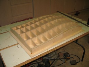
Assembled form for back support.

The support followed the curve of the rails, with the horizontal curves changing slightly from top to bottom to give lumbar support.

Click to view larger image.

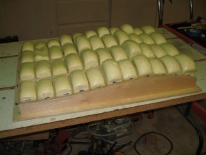
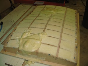
The form filled with expanding foam.

I used a stiff formulation of expanding foam to provide solid support for the fiberglass shaping.

Click to view larger image.

Filled form shaved to level surface.

Click to view larger image.

Needed a few repairs to fill some gaps.

Click to view larger image.

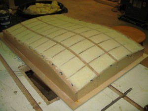
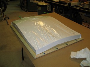
Form covered with heat shrink covering.

This covering is used on model aircraft.  It is stuck to the surface with an hot iron and then shrunk to fit tightly.

Click to view larger image.

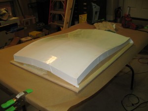
Form, all ready for fiberglass!

Click to view larger image.

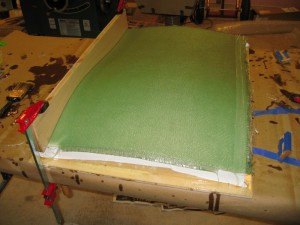
Fiberglass all cured.

Note the curved clamp on the top.  This was done to squeeze the fiberglass to a uniformly flat flange that will be used to attach to the rabbet in the back frame.

Click to view larger image.

Back support removed from form.

Unfortunately, even though I used an epoxy release agent on the form, the material still stuck to the back support enough that it tore away from the form when the cured fiberglass was pulled away.  It’s not a huge problem, I can easily put another cover on the form should I make another chair.

Click to view larger image.

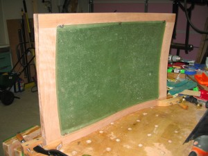
Fiberglass back support attached to the Back frame.

Note that I used tee nuts attached to the fiberglass ‘flange’.  They had to be trimmed to flatten the outside to get them to fit within the rabbet but this also prevented the nuts from spinning when the screws were tightened after upholstering the back support.

That’s pretty much it!  I did bring the pieces to a professional upholstery shop, I know my limitations!

Take care!


Replacing CNC Router Project

I’ve been using my CNC router pretty steadily since I first made it about 2 1/2 years ago and while it’s been quite useful and productive, the old DIY version has a few ‘idiosyncrasies’ that I wanted to address.  The more severe of these issues were:

  • With the main Y and Z tracks formed by two parallel pipes held in place with common 2X lumber, the spacing of the pipes would vary fairly largely as the humidity changed.  When expanding, the pipes would push the bearing wheels outward making the tracking tight, but the worst effect was after the wood shrunk again, the tracking would then be loose and have to be re-aligned before I could use the tool.
  • The Z axis, sandwiched between the Y Gantry plates ended up making the Z truck relatively narrow and, as a result, the router motor wasn’t held as rigidly in the X direction as I would have liked.  The effect of this were holes that weren’t round, inaccurate tracking on curves, and a system that was too ‘sloppy’ to try to mill aluminum – something I’d really like to try.

I didn’t see an easy way to modify what I had, since these problems were fundamental to the DIY implementation.  So, looking around, I found a router made by Carbide 3D that looked like it would meet my needs and further discovered that the mechanism (the part I really needed to replace) was available in kit form from Sparkfun!

This new mechanism is about 2/3s the size of the Old router (16×16 vs 24×24), but I never routed anything ranging larger than 15″ on the old one.  Hence the new one, being much more solid, promising faster travel speeds, AND not requiring realignment every time I want to use it, seems much more valuable to me.

I decided that this project needed to be done in three phases:

  1. Replace the old CNC router with new mechanicals, reusing the motors, electronics, and base from the old system.  I’d have to add another motor to the mix since the new system uses two motors for Y Axis.
  2. Replace the old base with a new base constructed out of T-Slot aluminum extrusions so that I would have a robust structure to which I could hold down soft metal parts for routing.  I’ll mount this on a cabinet that I can wheel around as conveniently as the current CNC router base.
  3. Finally, to achieve the full capability to route soft metals, replace the electronics with a faster processor, high voltage power supply, and more powerful drivers.

The first step, then, was to strip the old CNC router of it’s mechanicals, but, before I did, I needed to do two things:

  1. Flatten the base of the old router so that the new mechanicals would have a flat base to rest on.  The older bed had high spots as high as 1/32″ due to cupping of the slats I had installed.  Originally these had been trimmed to +/- 0.005″ over the entire bed.
  2. Make an adapter to mount the Bosch Colt router motor in the new system.  The new kit included an adapter for a Dewalt DW611 compact router, but the DW611 router is slightly smaller than the Bosch. I really like the Bosch motor and have invested in a number of expensive chucks primarily for CNC routing.

So, using the Old Router to plane its bed:
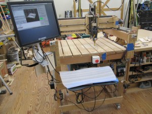
Click to view larger image.

Old CNC router planing its work surface to flat.

I’ve got a new flat surface and, taking a nice solid piece of hard Maple, I machined an adapter for the Bosch router.  I can buy an aluminum one, but these are shipped from China and I didn’t want to wait for weeks to get one.  This one will serve nicely until I decide to upgrade to aluminum…
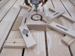
Click to view larger image.

Old CNC Router working on its last job. Making the mounting adapter for the NEW ROUTER!

By the way, the chunk of Maple was glued to a 1/4″ thick MDF waste board using CA glue and then the waste board was sanded off on my thickness sander.  Easy hold down technique!

I then stripped off the old gantry and removed the stepper motors.  WOW! What a job THAT was!  I had used Loctite Green on all the mounting nuts and set screws and it was a chore to free these up!

Building the kit was easy and in no time I had a new mechanism mounted on the old base!
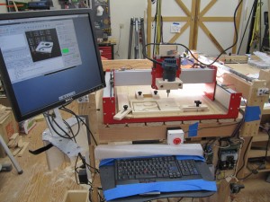
 

Click to view larger image.

New CNC Router mounted on old stand

Here’s a closer view.  The router had just finished its first job, a test pattern I used to test and trim the old router.  This first pass on this new router actually came out better than the LAST pass on the old router!  Yippee!
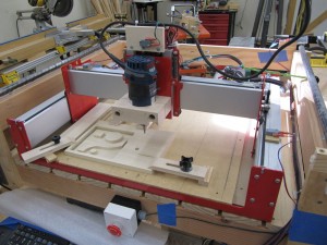
Click to view larger image.

New CNC Router finished first job with excellent results!

This new router uses a different drive mechanism than the old one.  The old one used conventional Acme screws driven by the stepper motors.  This new one uses GT2 treaded belts and the motor has a matching treaded pulley that literally pulls the assembly along the stationary belt.  The belt is very strong, but has a coarser pitch than the Acme screws I used so that the steppers need to be micro-stepped about 4 times for each step of the previous system.  This will give me faster travel (something I need to mill aluminum) but, until I replace the electronics, a slightly coarser finish.  Oh well, something to look forward to…
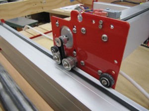
 

Click to view larger image.

Drive system for new CNC Router, Y axis shown.
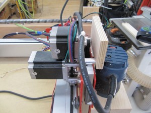
Click to view larger image.

New Router X & Z axis drives.

Finally, I can use the same folding setup from the previous router to fold up the system for storage:
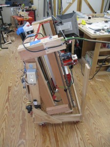
Click to view larger image.

New CNC Router folded up to put away.

I’ll be using this version for a while until I’m sure I’ve gotten it completely stable and then move on to the next phase of the project.


Hacking a toaster oven into a reflow solder station!

As I’ve moved into smaller and smaller electronic devices in my projects (and gotten older) I find that I can no longer reliably solder some of the components to the printed circuit board by hand.  I discovered that others had used toaster ovens for reflow soldering (Wikipedia link) where the printed circuit board solder pads are lightly covered with a solder paste, the surface mount components are placed on top of the paste, and the whole circuit board is heated in a sequence to solder all the components at once.

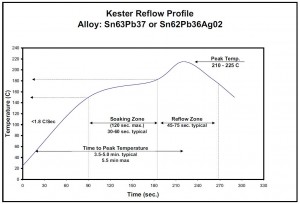
The sequence is supposed to look something like this (from Kester EP256 datasheet):


Click to view larger image.

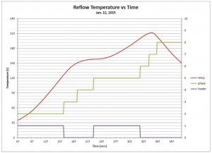
Here is what I was able to get with this oven:

Click to view larger image.

Here is the profile I’ve gotten with a bit of tweaking.

Close enough!  It takes a bit longer to reach target temperatures than the professional equipment, but mine uses FAR less power, and, what the heck, why do I care if it takes 5 minutes instead of 4 minutes to solder as many circuit boards as I have to do?

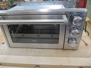
Here’s what the oven looks like:


Click to view larger image.

Front of the oven. Controls are timer, mode (I use convection mode), and temperature (max’d out).

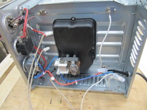
To convert, I had to take off the cover and rewire the controls.  I disconnected the silly neon lamp on the front of the oven and used its wires to power my controller and then cut the main power line feeding the thermostat and branched off both sides to the solid state relay I use to control the heating element in a more sophisticated way.

Click to view larger image.

Inside of the oven control section. Note the use of high temperature wire and porcelain wire nuts.

Even though I have an embedded computer controlling the heater, I decided to leave the original timer and thermostat in place to provide a layer of safety to this tool (even though it won’t be left unattended – unless I have to go to the bathroom, the UPS man is delivering something, etc etc etc).

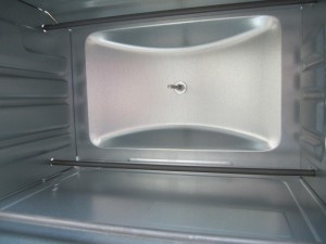
To monitor the temperature accurately, I installed a stainless steel probe K type Thermocouple.

Click to view larger image.

Inside of the oven with the shelves removed. You can see the stainless steel thermocouple that monitors the temperature right at the tray holding the workpieces.

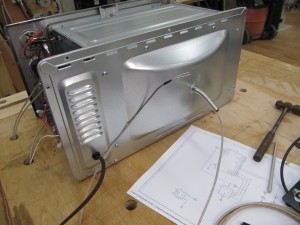
Here is how it is mounted from the back.  I was fortunate that this particular oven had the extended back (to provide room for the probe) AND had a little bumper installed exactly where I wanted to put the probe!  I just removed the bumper and ended up with a pilot hole to drill for the probe!

Click to view larger image.

View from the back. Note how the oven extends outward, providing room and a pilot hole for the probe.

The new controller was built from an Arduino type processor called ‘Moteino‘.  It is a very small circuit board and usually has an onboard radio for wireless applications, but, in this case, I didn’t need the radio.  It’s very easy to program this module, very small footprint, and, short of making my own PCB, about as low cost as I could get!  Of course, now that I have a reflow oven, I might be able to make my own board…

Click to view larger image.

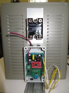
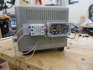
Mounted the new controls on the side. Shown is the new controller and solid state relay, which switches power to the heating element, mounted on a thick piece of aluminum to absorb any heat it generates.

Click to view larger image.

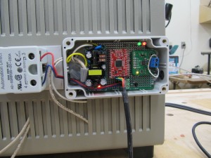
Close up of the controller. The red circuit board is the ‘smarts’ of the device while the circuit to the right converts the thermocouple signal to an accurate digital value used by the controller.

The red and green lights in the upper right are used for status.  The red light’s intensity is proportional to the current temperature in the oven.  The green light flashes based on which phase the sequence is in. And BOTH lights flash demandingly when I need to open the oven door to accelerate the cool down.

Click to view larger image.

Here it is, all buttoned up and ready to solder circuit boards!


Happy New Year!

New Year’s Day?  Pshaw!  It’s just another day at the ‘office’!

Click to view larger image.

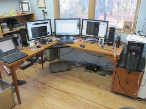
Just another day at the office…

Here’s my current ‘activity’ as I’m simultaneously debugging code on 4 different processors, 3 of which have radios that are communicating with each other and one is our home server containing our webserver and MySQL database (where all the data is supposed to be going).

Amazingly, it’s all working!

Cheers!


WordPress theme: Kippis 1.12