New additions to the CNC Router

Air Jets

After doing the Pottery Logo project, I realized that I need to have air jets to both cool the router bit and clear away chips.  With plastic especially, but even with wood, the chips, if not cleared, will collect in the channels and create friction, and, eventually, burn the router bit (and scar the walls of the workpiece).  I found some nice flexible hose components that allow you to easily guide the air to specific spots.  The ‘hose’ consists of small hollow knuckles that snap together like beads and, with the friction fit, stay where you bend them.

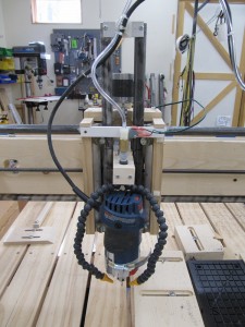
Here is the setup I’ve installed on the Router:

Click to view larger image.

Z Gantry with new air cooling/clearing jets added.

The mounting block moves with the Z Gantry and keeps the air nozzles pointed at the router bit.  I’ve supplied the air through a solenoid valve that is controlled by the CNC commands so I can turn on the air only when the ‘chips are flying’…


Vacuum Chuck

In the course of doing various projects on the router, I’ve concluded that ‘hold downs’, the devices needed to keep the workpiece in place, are the biggest nuisance of doing any CNC routing.  The first problem is that they inevitably get in the way and, being in the way of a XYZ gantry, with a very sharp tool spinning at 24000 RPM, is generally not a good thing…  Bad things ALWAYS happen in this case.  The hold downs get in the way because they aren’t part of the model that you’re working on and are ignored in the ‘flight path’ when generating the CNC commands!

The second problem is, they don’t always hold the material flat.  If you have a thin, eg 1/4″ thick, strip of wood that is 6 inches wide, holding down just on the edges is not sufficient.  It will most likely bow, to some degree, in the middle.  If you’re trying to engrave with a V bit and the total depth of engraving is only 0.032″, even a 0.010″ bow renders the engraving useless – there is too much width variation in the engraved lines.

So, what’s the answer to both these problems?

I’m hoping that it’s a Vacuum Chuck.  A Vacuum Chuck in a device that clamps to the CNC Router floor and uses vacuum to hold down the workpiece.  How well does vacuum work?  Let’s see… if the chuck is 12″ x 6″, that’s 72 square inches.  If the vacuum can be >10″ of mercury, that’s equivalent to 5PSI.  5 pounds per square inch x 72 square inches is a hold down power of 360 pounds!  Probably ok for most things…  AND the pressure is evenly applied across the entire surface of the workpiece.  Consequently, that 1/4″ thick piece of wood is FLAT and stays FLAT!

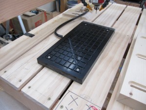
Since I have the equipment to do vacuum pressing for bent laminations and that included a plexiglass block with a vacuum port, all I had to do was use the router to create air passages across the face of the block and, with the Pottery Logo Project, I had just the router bit to machine the plexiglass!  Here is the result:
Click to view larger image.

Vacuum Chuck with a mesh of air passages across it’s top. The air passages all lead to the vacuum fitting at the left, center of the plexiglass block.

With Chuck all machined, I was anxious to try it out.  The first thing I did was put a piece of 1/4″ MDF on the top and turn on the vacuum.  Boy, did THAT suck!  Or, I should say, it didn’t suck.  I was hardly able to get 5″ of vacuum (perfect vacuum is approximately 29.9″ or 14.22PSI)!  Major disappointment!

After trying various things to seal the edges, thinking this was where the air was being lost, and actually sealing the edges with double sticky tape, I realized that I was losing air THROUGH the MDF!  The MDF is so porous that it was actually letting air bleed through its entire surface.

Hmmmm…  I looked around and noticed one of my scraps of MDF had been sprayed with Shellac.  I grabbed that piece, put it on the double sticky tape and the vacuum immediately rose to 17″!!!  Then, further realizing that that piece of MDF had never been sanded after the Shellac, I sanded down the ‘fuzzies’ with 600 grit sand ‘paper’ and was able to get as much as 22″ of vacuum.  GREAT! That’s over 770 pounds of holding power!  Now we’re talking!

This was great news, because part of the plan was to use MDF as an interface between the chuck and the workpiece if I need a ‘spoil board’.  A ‘spoil board’ is a board that gets ‘spoiled’ in the process of routing a workpiece when the workpiece needs to get cut all the way through.  You can safely cut through the workpiece into the spoil board and won’t dig into your CNC Router bed or, in this case, vacuum chuck.  Basically the MDF spoil board will provide air passages from the chuck to the workpiece and the workpiece will hold the spoil board sandwiched to the chuck.  Key is that the air passages in the spoil board need to be placed where the workpiece won’t get cut through, otherwise the vacuum will be lost and, uh, bad things will happen…

Good examples where I’m hoping to use this method is when I’m making small pieces like key fobs or coasters.  I can set up a spoil board for each type of project and reuse it as often as I need.

Another thing I need to do, where this chuck will help, is in cutting up printed circuit boards (PCBs).  I’ve been doing a few electronic projects recently and some of them are fairly small boards (1″x1.9″).  PCB manufacturers generally try to get you to fit your board within certain fixed sizes, with the smallest size typically 5cm x 5cm (1.93″ x 1.93″).  Obviously, I can fit two of these designs on to this minimum size.  In the ‘old days’, when I’ve combined boards into a single PCB, I’ve used a bench shear to cut the boards.  This works ok, but the boards get scuffed and slightly bent in the process.  A better approach is to cut a V groove on the dividing line on both sides of the board so it can be simply snapped in two.  Hmmmm, sounds like a job for a CNC router!

So, may I present, for your consideration, an MDF alignment/vacuum interface board for cutting a PCB:
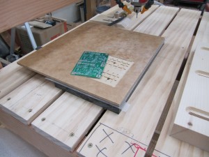
Click to view larger image.

Vacuum Chuck with MDF interface providing an alignment well to machine the PCB. Note the air channels in the PCB well and the holes leading down to the chuck.
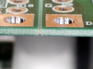
Click to view larger image.

Here’s a close up of the PCB after being machined on both sides. This is perfect! Very ‘snappable’! The PCB is 1/16″ thick.


The Little House in the Village Kitchen Cabinets Are DONE!

Yippee!

Finally, after much planning, work, and scheduling (not to mention diversions that had nothing to do with the LHV!), the Kitchen Cabinets are done* and we have a usable kitchen that we enjoy!

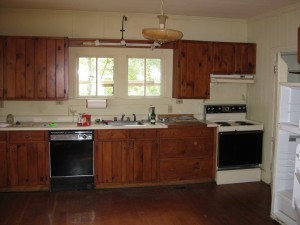
Here is what we started with!

Here is the original kitchen.

Here is the original kitchen.

And here are a few ‘glimpses’ of the finished product:

In case you’re wondering about the two cabinets that don’t have doors, the corner cabinet was built in place so the door was assumed to be custom fitted.  The doors for the cabinet over the dishwasher were, uh, ‘overlooked’ in the fab sequence.  These two cabs will have doors added next ‘visit’ to LHV…


Notes:

[*] In this case, ‘Done’ means that we won’t need to haul 1000 lbs of material and tools to the LHV to finish it!


The “Throwaway” Buffet Cabinet

In our kitchen at the House in the Woods, we have one spot that desperately needed a cabinet.  Not only because the space was vacant, but because we really needed a place to store our collection of cookbooks (and another horizontal surface wouldn’t be a bad idea either).

Kerry decided to look for an inexpensive cabinet from Overstock etc. so we could fill the space quickly.  She found a number of candidates, but all of them were too large or wrong shape for the space we had.  Rather than having an off-the-shelf cabinet look clumsy in the space, we agreed that I would make a knock off of the off-the-shelf unit, but re-sized to fit the space.

Here is the original cabinet:

Click to view larger image.

Original cabinet idea.

The first change I wanted to make was to replace the glass with something opaque since we didn’t want to keep the cookbooks in a nice neat order required if they were visible.  In this case, solid panel doors would have worked but I thought it might be ‘interesting’ to use the four side by side panels to ‘tell a story’.  At first I thought of panels engraved with Kanji symbols, something I could easily do on the CNC router.   You know, something like Life, Health, Happiness…

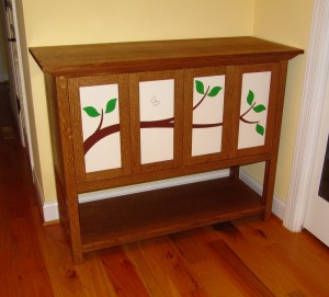
However, Kerry thought something that was more a ‘picture’ would be better and, after spending a few days researching, came up with a nice stylized ‘branch’ that could flow from one panel to the next.  I liked it!

Here is the result of the paneled doors:

Click to view larger image.

Doors with engraved and painted panels.

Finally, as you can see from the doors above, I decided that, rather than have some nondescript ‘brown wood’, I used quarter sawn white oak, stained with a dark tung oil.  Here is the finished cabinet (still waiting to harden enough to wax).

Click to view larger image.

Finished cabinet, ready to be loaded with cookbooks!


Yet Another Method to make (almost) perfect Knife Hinge Mortises

I’m working on a Buffet/Sideboard cabinet for our kitchen at the House in the Woods and, because it has four side by side inset doors, have decided to use Knife Hinges to mount the doors.  Knife Hinges are very discreet, barely visible and allow the two center doors to be mounted back to back, without a center post.

The tricky part about Knife Hinges is that each blade of the hinge must be precisely mortised into the top and bottom rails and the top and bottom edge of the doors and there is no adjustment for positioning (unless you make the mortise oversized).  The blade is flush with the wood surface and the only part that is exposed is the pivot.  Each pivot has a spacer which precisely defines the top and bottom gaps for the inset door.  For appearances sake, the right and left gap of each door should match the top and bottom gaps.  Therefore, the door is sized to fit the opening with this small gap at each edge of the door.

With the hinges I’ve purchased (5/16″ Brusso hinges) the spacer is 0.048″, halfway between 1/32″ and 1/16″.   This means that the hinge positions for the right and left hinges must be precisely 0.048″ from the right and left legs, respectively AND, even more tricky, the center two hinges must be positioned 0.024″ from the center of the rail AND must precisely line up with the corresponding mortise on the opposite rail.

WHEW!

As I thought about what technique to use to make these mortises in the quarter sawn oak rails I realized that each mortise is identical to each other.  Some are mirrored, but the dimensions are identical.  Further, trying to chop out a mortise with a 0.048″ end wall or a pair of mortises with a 0.048″ wall between them, I knew that chopping with a chisel wasn’t an option.  That meant the best way was probably routing.

My first thought was to use my CNC Router to make a jig for a hand held router, but then, after a flash of light! I knew how to make these mortises!

The rails are 40 1/2″ long so I couldn’t cut all mortises in one pass (the CNC router is limited to 24″ of travel).  However, since the mortises on the top and bottom are identical but mirrored, it would be easy to design the pattern to cut TWO mortises at once with the two rails clamped together face to face!

Further, with the two rails perfectly aligned, the top and bottom mortises would be perfectly aligned.  AND if I took shallow passes on the cutting, then there was a good chance that the thin end and center wall could be maintained.  Finally, the FOUR center mortises could all be cut in one pass so the hardest alignment should be easy.

So, here ya go…

Click to view larger image.

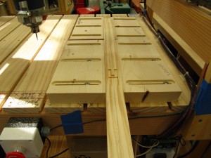
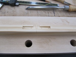
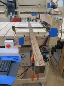
Here is the prototype, just to make sure the pattern and technique would work.

You can see the center mortises precise cut in the two rails.  Here is the fitting of the hinges to the mortises:

Click to view larger image.

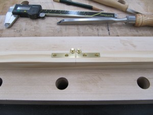
To fit the rectangular hinge, I needed to trim the 1/32″ radius corners.

Click to view larger image.

Here are the two hinges mounted back to back. The spacing is exactly 0.048″!!!

Now it was time to do the REAL rails!  Here are the oak rails (with first coat of tinted oil) with all the mortises cut.


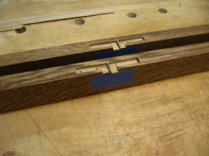
Click to view large image.

All eight mortises have been cut. Unfortunately, I messed up cutting the center mortises!!!

When I set up the rails to cut the center mortises, I reloaded the CNC program and forgot to tell the CNC software that the cutting bit was already mounted.  When I began the alignment to the center of the rails, the software tried to move the router lower than the bit would allow and I needed to realign the bit after it got pushed in slightly.  Unfortunately, I didn’t tighten the collet well enough and, while routing the first set of center mortises, the bit slipped and cut the mortise about 0.088″ deeper than it should have!  Pooh (this is what I said at the time, I’m sure of it…)

Ok, the secret to ‘fine’ woodworking is knowing how to cover your mistakes…

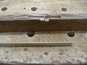
Click to view larger image.

The two center mortises, one deeper than the other. In the foreground you can see a piece of oak that I machined to exactly 0.088″ thick…

Click to view larger image.

Here are the two mortises repaired with the fillers. All mortises are back to the same depth and, after the glue dries, the excess will be trimmed off and stained. No one will ever know ;-)

To make the hinge mortises in the doors, the CNC router would be difficult since the mortise is cut into the ends of the 18 3/4″ stiles and I’d have to jury rig some kind of reliable mount with most of the door hanging under the modified CNC base plate – Yuck!

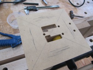
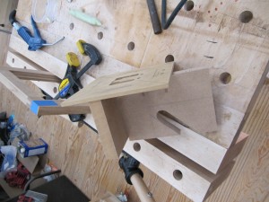
Instead, I used the CNC router to make a routing template that could be clamped to the door and hand routed with the trim router.  Here is the jig I made.

Click to view larger image.

The CNC router cut the 1/4″ MDF sheet with mirrored openings for the top and bottoms of the doors.  The extra holes were used to temporarily screw 1/4″ bolts used as guide pins to align the center clamping block.  This gave me a reference edge for the face of the door and allowed the guide to be perfectly aligned when clamped.

Here are some underside views of the Jig.

Click to view larger image.

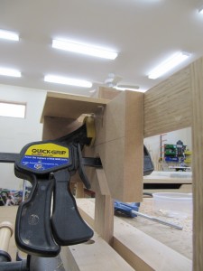
Under side of the jig with slot for clamp.

Click to view larger image.

Here is the jig clamped to a door.

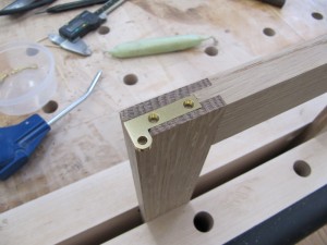
Finally, here is the result of mortising the door with hinge inserted into mortise.

Click to view larger image.

Finished Mortise with hinge inserted.


WordPress theme: Kippis 1.12